🤖 Merlin's Gem Bot — User Manual
IntroductionSafety InstructionsComponents and AccessoriesSetupBasic OperationTouch Screen ExplainedMaintenanceTroubleshootingContact and SupportIdentifying Parts of the Machine

By. Ryan Barbrick 2024
Introduction
Welcome to the user manual for Merlin's Gem Bot Automated Faceting Machine. This guide will help you set up, operate, and maintain your Gem Bot to ensure optimal performance and longevity.
Table of Contents
- Safety Instructions (page 2)
- Components and Accessories (page 3)
- Setup (pages 4-7)
- Operation (pages 8-48)
- Maintenance (page 49)
- Troubleshooting (page 50)
- Contact and Support (page 51)
- Identifying Parts of the Gem Bot (page 52)
Safety Instructions
- Read Instructions Carefully: Before using the Gem Bot,
thoroughly read this manual to understand all operating procedures and safety precautions.
- Electrical Safety: Ensure the machine is plugged into a 110v
properly grounded outlet. If you are using this machine outside of the United States and are running off of a 220v plug you will need to obtain an electrical converter to convert from your foreign plug to US standard 3 prong 110v plug.
- Keep Area Clean: Maintain a clean workspace to avoid
accidents and ensure the machine operates efficiently.
- Personal Protective Equipment: Always wear safety goggles,
a dust mask, and gloves when operating the machine. Keep loose clothing and or hair away from any moving parts of the machine.
- Supervision: Never leave the machine unattended while in
operation. Always make sure to keep a close eye and ear on the machine. There is always the possibility that a stone may come detached from the dop stick and go flying.
Components and Accessories
The Gem Bot package includes:
- 1 x Gem Bot Automated Faceting Machine
- 1 x Set of Dop Sticks
- 1 x Set of 6 inch Diamond Grit Grinding Wheels
- 1 x 6 inch Copper topper Polishing Wheel
- 1 x Set of Diamond Polish Compound
- 1 x Set of Miscellaneous Tools for Maintenance and Use
- 1 x Transfer Pad for helping align stones on different sized dop sticks
- 1x Touch screen controller for controlling the Gem Bot
Setup
1. Unpack the Gem Bot with care and inspect for any shipping damage. Try not to lift at 3D-printed part locations. Make sure not to snag any wires, as these will need to be connected to the lower unit for the upper motor control and switch control. Try to lift from the upper front and back aluminum frame rails on the upper assembly. For the lower lift, I would recommend a two-person lift. Lift from the bottom and bend with your knees; make sure to communicate; and don't forget to make sure your drawers are shut and secure when lifting to avoid any damage. Maybe get the lower to the place where you wish your machine to be setup before installing the upper onto the lower. If your machine was shipped in two pieces, You will need to set the upper unit onto the lower unit and secure it with the supplied screws. There should be screw holes to line up with already in place on the lower unit. The Upper Unit lower rear rail should sit flush with the back edge of the base. The lower right rail of the upper should sit flush with the right side of the base. 2. Place the machine on a stable, level surface. I like to put mine on the floor. And pull up a nice desk chair while cutting. Also the touch screen wont drop too far if it is already on the ground. Planning to make a more robust case for the touch screen soon, and hopefully do some wireless controls so that the touch screen is not tied to the machine. 2.2 Connect the upper connectors to the lower connectors. There should be a total of 7 connections. They should all be labeled. 1-Angle Control Motor, 2-Angle Set Switch, 3-X Motor Control, 4-Y Motor Control, 5-Index Motor Control, 6-X Switch, 7-Y Switch
2.3 Unpack the touch screen with care and make sure that it has its SD card with design files on it (located in the back). Plug the touch screen into its supplied plug. The cord for this is located on the right side of the machine, most likely near the front of the machine. The wheel sits on the left of the machine when facing forward. The wiring should be on the rear rails. 3. Connect the power cord to a suitable power outlet of 110v . For international machines, please use a power converter. rated for max. 1200w (that is what the smart surge protector is rated for). Everything is pretty low-wattage and low-voltage in the whole setup, though. 4. Turn on the power switch located on the right side of the machine. It is a blue circle. This is also your kill switch if you ever need to cut power to the machine quickly, say if you notice the stone is running into the wheel. Always try your best to power down during pauses in the cut function and remember to always make sure your index is set to 96 on power down so that when the machine powers back up it will load that position as being set at the 96th index. 4.2: Run a switch test and make sure your switches are functioning. Follow the on-screen instructions. Be careful not to break anything when pressing these switches. It is important to make this a common practice to avoid collisions and cut function failures or home function failures. 5. Calibrating your machine: Setting your 90-degree set screw so that it comes into contact with the angle-set switch when the stone or dop stick is at 90 degrees. Start by installing a dop stick with no stone on it into the chuck and tightening it down by hand. Enter the manual controls via the touch screen. Press 90° to set your angle control arm to 90°. Make sure not to make any X and Y movements during this process so that the x and y axes are easier to move by hand. Once these motors receive a button press to move in any direction, they will be charged up and will be more difficult
to move by hand. The goal here is to set your dop stick flat on the master lap. Adjust your angle trigger/set screw carefully by hand. You want this screw head to come into contact with the switch as the dop stick is flat on the lap. This will be your 90 deg. 5.2: Make sure your grinding wheel spins up. Install your master lap, washer, and tighten the arbor bolt. This is reverse threaded; spin counter clockwise to tighten and clockwise to loosen. Sometimes you may need to push down on the lap or hold the lap in place while getting the nut nice and tight or while trying to get it loose. Make sure the knob on your motor controller is turned all the way counter clockwise. This sets the speed to zero. The controller for the main electric grinding motor is located on the left-most portion of the lower unit's top surface. It is rectangular with a digital readout and a few buttons that control power, rotation direction, and digital display settings. A knob to control speed. And a power switch to turn the motor on and off. Press the power switch to ensure power to the motor; you should hear this when it is powered on. Make sure your display is set to rpm output if that is what you desire to see. Slowly turn the speed control knob clockwise to the right to start spinning the wheel. You will find that this is nice and quiet and should be spinning very true with minimum to no wobble if everything is installed correctly and not spinning loosely. You will want the motor on low for checking your drip during the next step. You can also do a drip test with the wheel off and the electric motor off if you would like. I like to do this to check for leaks around the center drip pan hole and around the screws for mounting the drip pan to the metal base. Silicone has been added in these places, but it is always a good idea to keep an eye on these places, especially after cleaning. You should not run into leaks there, but if you are running a high drip rate, you may run into the drip pan filling up too much and put those seals to the test. I usually like to use my machine on the lowest possible drip. It is enough to remove the cut material from the lap, I believe.
6. Testing the Drip In the lower drawer, there are two containers. The one on the left is for returning water from the drip pan, and the one on the right is the water reservoir for sending water up to the wheel. The drip motor is towards the back, between the two bins. There is a return line coming out of the back of the return bin. There should be a smaller line coming out of the lid of the sending bin. This line tip should be at the bottommost point of the sending bin to ensure water flow. To test this system, I usually leave the bottom drawer open so I can peek behind it and make sure I am not leaking from the top. This is something that you should always try to be aware of. Make sure your water isn't getting where you want it. Ideally, all water should be returned to the return bin. If you are on the lowest drip setting, you should have hours of drip before you need a refill on your rez. The user is responsible for any water damage that may occur. It is the user's responsibility to make sure their machine does not drip where they do not want it to. We have done our best to secure any electronics away from any liquid. After the setup is complete we can go ahead and get a stone set onto the dop stick. There are many ways to do this and no one way is the definite right way. Here are a few videos by Austin Moore that will help with the dopping process. Gemstone Dopping - Faceting Lesson 3 Dopping a gemstone with Super Glue - Faceting Lesson 4
Basic Operation
- Power On: Turn on the machine using the main power switch.
- Touch Screen Interface: Use the touch screen controller to select the desired gemstone
design or input your custom design. Manually control movements or follow the on screen instructions for automated cut motions.
- Loading the Gemstone: Attach the rough gemstone to a dop stick and insert it into the
machine’s chuck. Make sure everything is as center and tightened snugly as possible. Use the correct size collets within your chuck to match your dop stick size.
- Cutting Process: The machine will automatically adjust and cut the gemstone based on
the data tables per shape and design.
- Monitoring: Regularly check the machine’s progress and ensure it is operating correctly.
There are a few different cutting options to select from. Make sure to start with the basics, so that you know how your machine is suppose to be moving. Take the time to watch the supplied how to videos that can be found on the home page of the Merlin’s Gem Bot website. I took the time to make these videos for you, so please watch them if you are planning on becoming a Gem Bot user.
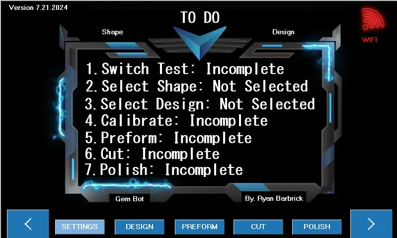
Touch Screen Explained
When you turn on Gem Bot the touch screen will look like this. This is the To Do list. As certain tasks are completed the White Text will turn to green. 1. Switch Test: The switch test should be ran every time the machine is powered on to make sure the Gem Bots limit switches are functioning properly. This let the machine know where its components are at within the 3d world. There is an X axis limit switch, a Y axis limit switch and a limit switch for the angle control so that the machine knows it is

set to 90 Degrees and can calculate the cutting angle based off that initial 90 degree set point. 2. Select Shape: This will turn green once a shape is selected and the “Shape” text in the upper left will change to whatever the selected shape is. 3. Select Design: This will turn green once a design is selected and the “Design” text in the upper right will change to whatever the selected design is. 4. Calibration: The calibration text will turn green after the machine has been calibrated. Calibration for the machine is not necessary to preform, cut, or polish a gemstone just yet. As we are setting the stone to the wheel. Later these calibration tools will be used to further automation. 5. Preform: This text will turn green after the preform function is ran. 6. Cut: This text will turn green after a cut function has been completed. 7. Polish: This text will turn green after a polish function has been completed. As you can see there are Two arrows (< >) on the bottom left and bottom right of the machine. These are used to navigate through the touch screens menu. From this main screen we can see that the “Settings” Button is highlighted a lighter blue color. If we click this we will be able to access the Gem Bots “Settings Menu” we will cover this on the next page of the manual.
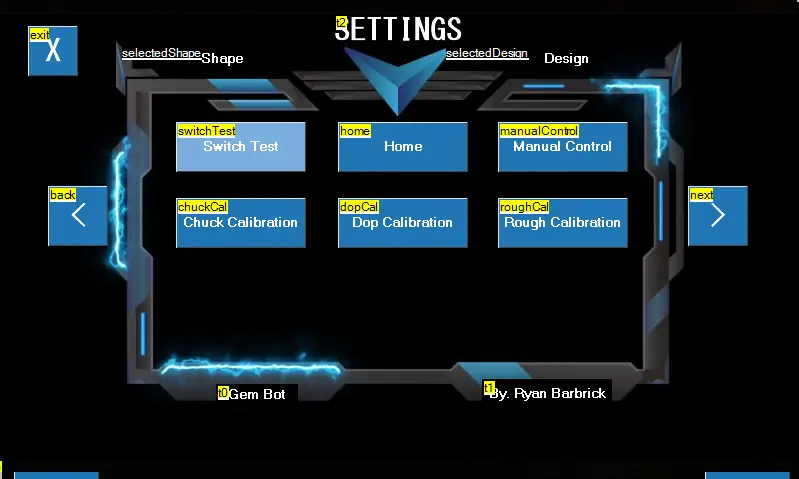
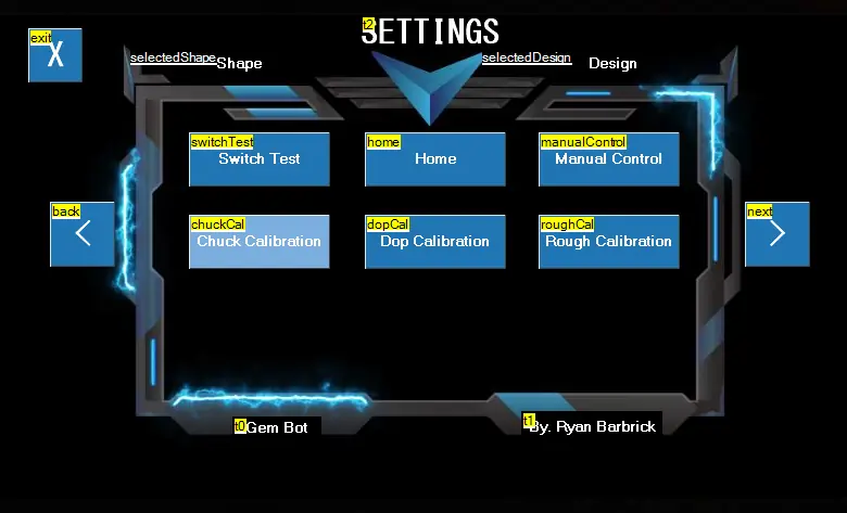
Here you can see we have accessed the “SETTINGS” page. From here we can run our switch test, A home function, access our manual control page, calibrate our chuck, dop and rough stone dimensions. As you can see there are two arrows on the left and right side of the screen to navigate through the menu. You will see that the color for the selected menu item is a lighter blue than all the other menu items. If you then click on the highlighted button it will take you to the corresponding touch screen page. You can also use the X button in the top left to exit the Settings page. Lets jump into the Switch Test Page by clicking the highlighted Switch Test Button. I will cover this on the next page.
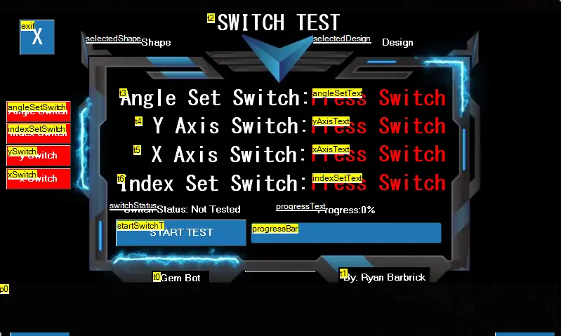
Here we are on the “Switch Test” Page. We will use this to make sure our limit switches are functioning properly before we run any cut functions. The Gem Bot uses these limit switches to tell the machine that it is at its home location. To run this test we will simply click the start test button. We will first press the physical Angle Set limit switch on the machine, The Y axis Limit Switch and the X axis limit switch. As these switches are the Text in red to the right of the switch definition will turn green and say that the switch is working properly. If for any reason when running this test and the corresponding limit switch does not seem to be working. Check your wiring and make sure the switch is plugged in. Check you switch for any damage. If you are prompted to press the angle switch and the y axis switch triggers that the test is working this is a sign that you may have your wires swapped. All limit switches are tested before the machines are sent out. If you find that one of your limit switches is not working and cannot diagnose the issue yourself. Please do not go into any further machine functions and contact support so we can help you diagnose the issue and or get you a replacement switch. After the Switch Test is complete we will be automatically taken back to the SETTINGS page.
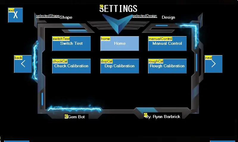
As you can see we have used our right arrow to highlight the “Home” Button. If we click this we
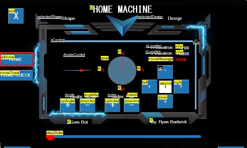
will be taken to a control screen that will become very familiar through the machine.
You can see the title at the top of the screen now. We are on the “Home Machine” Page. We will not be limited to homing our machine from just this page. But it is an option. To home your machine you simply click the “HOME” Button and then the “Home Check” Button will appear after the machine is homed to make sure we are in fact completely homed. If we do not click the Home Check button our next home function pay contain an error where just the angle is homed to 90 degrees. After we have Homed the machine and the x, y, and angle are at their home positions we can go further into the cut process. It is not necessary to enter this home screen every time. And there are other buttons within the different cutting methods to home the machine. You can press the X at the upper left of this page to get back to the settings page. Next we will go into the manual control settings. Where all the magic really happens for controlling and moving the machine.
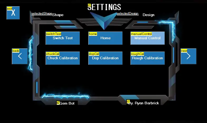
As you can see we have used the right arrow to navigate through the menu and highlight the Manual Control Button. Once highlighted we can then click this to open the Manual Control Page. One of my favorite pages for controlling the movements of the machine.
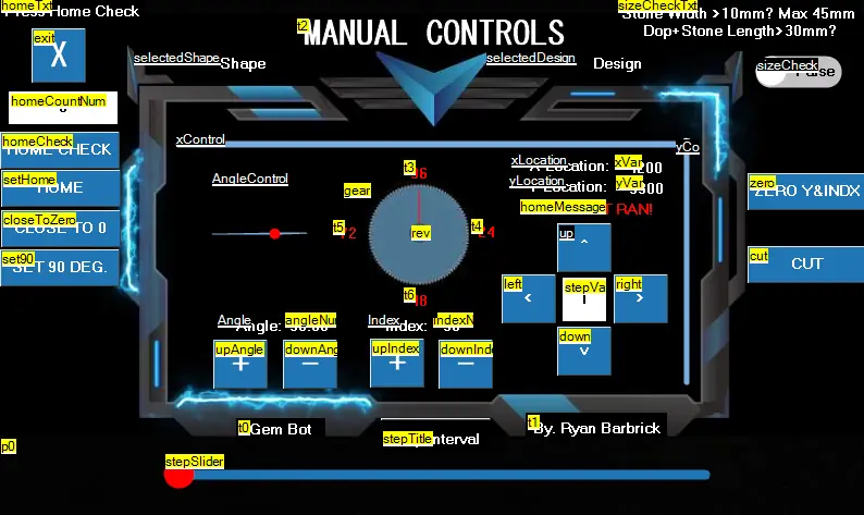
This is our manual control page. With this page we can control all the movements of the machine. We can use these controls to manually cut stones with precision and have digital outputs such as X and Y Location, Angle output, and index output. I will go through every button on this page so that you know what each button does.
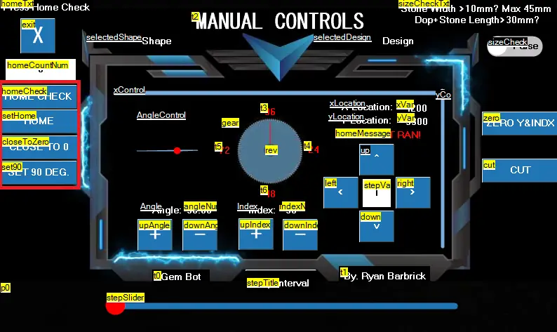
We will now go over these four buttons on the left. The Home Buttons, The close to 0 and Set 90 Degrees. The home and home check buttons will set the machine to its home position. When this button is pressed, the Y axis will first raise until its limit switch is hit, it will then lower 100 steps so that the switch is depressed. It will then move on the X axis in the right direction until it hits its limit switch, it will then move left 100 steps so that this limit switch is depressed. The 90 degree angle will then be set. First the angle will lower a few degrees to make sure the angle set switch is depressed and move back up until the angle set switch is triggered. This will set the machine to 90 degrees so that it can increment down or up and calculate future angles to be set to. The close to 0 button will show up only after a home function is ran and the machine is at its home position. This will quickly move the machine to the left and lower the y axis so that less button presses are needed to move the stone closer to the wheel. The set 90 degree button can be used to just home the angle motor to 90 degrees if you do not wish to run a complete home
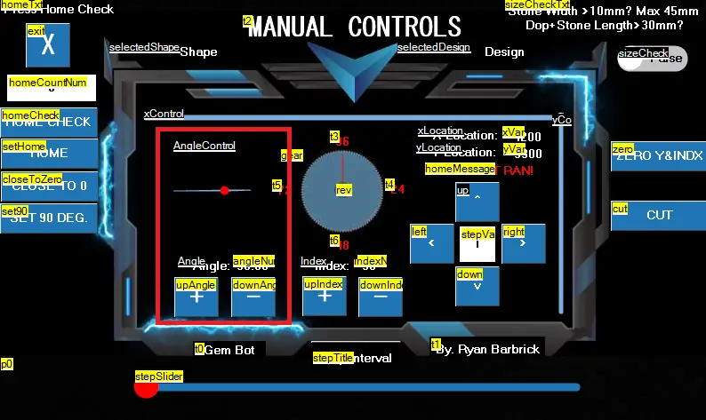
function.
Here we can see the Angle Control Buttons. There is a “+” and “-” button. Numerical digital readout and a graphical display of what the actual angle is set to. We use these buttons to set the angle of the machine after the home function or set 90 degree angle buttons have been pressed. We have a range of 90 degrees to 0 degrees of movement here. With each click of the up or down angle button equaling .36 degrees of movement. The angle motor on the machine is attached to a planetary gear box with a 5 to 1 gear ratio. This allows for 1000 steps per 360 degrees of motion from the stepper motor. We can not move the machine higher than 90 degrees and we cannot move the machine lower than 0 degrees. I have limited this
programmatically. Next we will look at the index controls.
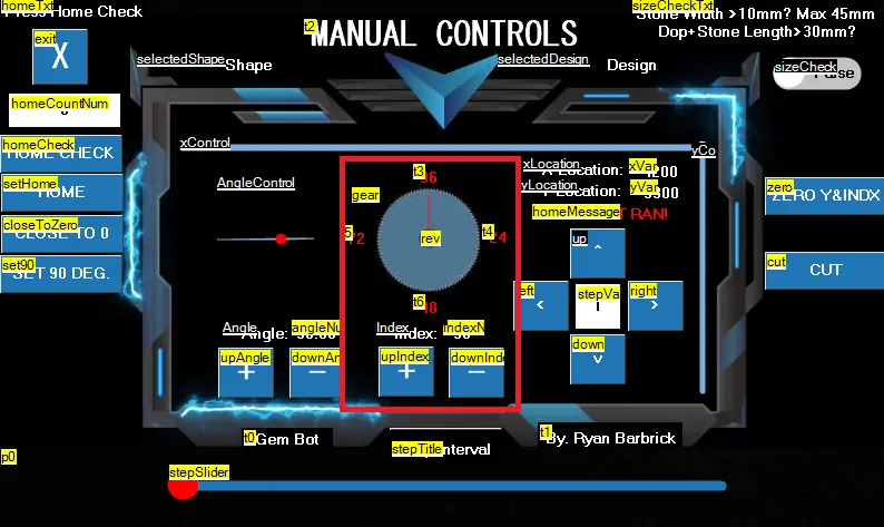
Here we have our index control buttons with digital numerical readout and an graphical display of the index wheel. The gem bot runs off a special stepper motor that allows only 96 steps per single 360 degree revolution. That is 3.75 degrees of movement per step in either direction. Just as the standard index gear is on many manual faceting machines and what many faceting designs are geared for. We can use the “+” and “-” buttons here to control our index location. We want to make sure after using our manual controls for cutting that we set out index back to 96 before exiting or powering down so that when the machine is powered back up we will load back up at our default 96th index location. When incrementing up or down with the index controls we can go from the 96th index and press the up index button and it will take us to the 1st index. We do not have to press 96 times on the down index button to reach the first index. Same goes for going from the 1st index location to the 96th index. We do not have to press the up index button 96 times to go to the 96th index we can go directly from 1 to 96 by pressing the down index button. There is a toggle button added in a recent update located in the center of the graphical index gear. We can click and select this if we find that out physical index location is
moving in the opposite direction than what our digital readout is moving. Reversing the movement. Next we will look at the up and down, left and right/ x and y movement controls.
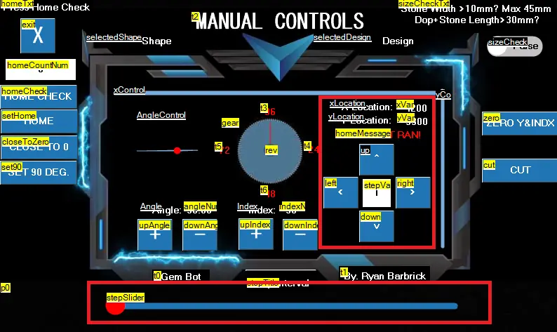
Here we can see the buttons for the up and down, left and right controls. Each single step of the x or y axis in either direction is equal to .018mm of movement. In the center of the 4 buttons we have how many steps we will move per button press in whatever direction. We have a step slider highlighted below. This will allow us to adjust the number of steps we will be moving per button press. This will help us speed up movements and require less button presses from the user during manual cutting or while setting the stone to the wheel. The step slider ranges from 1 to 70 steps per button press. If we press the left button the x axis will move left. If we press the right button the x axis will move right. If we press the up button the y axis will move up and if we press the down button the y axis will move down. Pretty simple there. Above those 4 buttons we have our digital X and Y location readout so that we know where the stone is after a home function is ran and after we have moved the stone around some. You can also see an xControl Slider up top and a y control slider to the right. There is a tiny white ball that moves on that slider representing the x and y location in the physical realm.
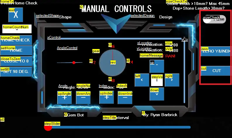
Next we will go over the buttons to the right.
On the right of the screen we have 3 buttons. The top button is a toggle switch for moving the stone not so close to the wheel but still close to the wheel. If the stone is larger than 10mm and or the dop + stone length is longer than 30mm will click this toggle switch so that the stone does not run into the wheel for larger stones and longer dop sticks being used. The second button is the zero Y and Index. These buttons are used if we accidentally power the machine down or need to reset our index location to the 96th index. The third button is a great little button for some quick left and right swiping motion and a single step down on the y axis for use when cutting with our manual controls. I like to use the manual controls allot for various functions. Sometimes I use the manual controls to figure out how much depth is needed to cut per facet. Or maybe I am experimenting and trying to create some special designs. I can use the manual controls to move the machine how I want to move the machine while cutting and not be limited to the preset automated cut functions and designs. Maybe I need to get a better polish on just one facet. I can achieve this with the manual controls. The manual controls can also be used for checking to see if motors
are functioning properly and machine movements are in fact moving how we want them to move. The manual control functions were the first things that I initially programmed to make sure all my wiring of the motors were correct. I like to use the manual control functions to also give me more of a hands on feel when cutting a stone sometimes while also having the accuracy and assurance from the digital readouts that I am cutting at the correct location on the stone. These controls are great for diagnosing errors that the machine may be having and ultimately just getting a general idea for how the automated cut functions should be moving or how I could possibly improve on the automated cut functions. We can exit the manual control page and get back to the settings menu by clicking the big X butt in the upper left hand corner.
You can see now that we are back on the SETTINGS page and we have the Chuck Calibration Button highlighted by using our “>” right button navigation arrow. We can now click the Chuck Calibration button to enter the Chuck Calibration page.
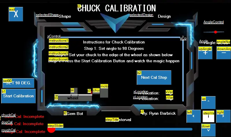
Here you can see the chuck calibration page. With some simple instructions up top. First we will click set 90 Degrees button on the lower left there and set the edge of the chuck to the edge of the wheel as shown in the graphic there. We will use the x and y axis controls on the bottom right of the page to control the movement of the machine. We will press the Start Calibration button and it will run a home function counting each step on the y and x axis to give us a zero point to go back to so the machine knows when the chuck is at the wheel. The machine will also use this data to calculate dop dimensions based on the calibration of the next page. We can see some red text in the bottom left there that shows what we have successfully calibrated and what else we need to calibrate to help with the automated cut functions. As of now we are setting the stone to the wheel so these calibration pages are not really needed for successfully cutting a stone. In the near future these pages will be used to give more data to use for the automated cut functions. If you made it this far I think you should know how to navigate the touch screen menu a little bit. So I will just show off the next few calibration pages.
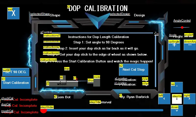
Here you can see the dop calibration page with some instructions for getting some dop data. This page will be used to get the dop length.
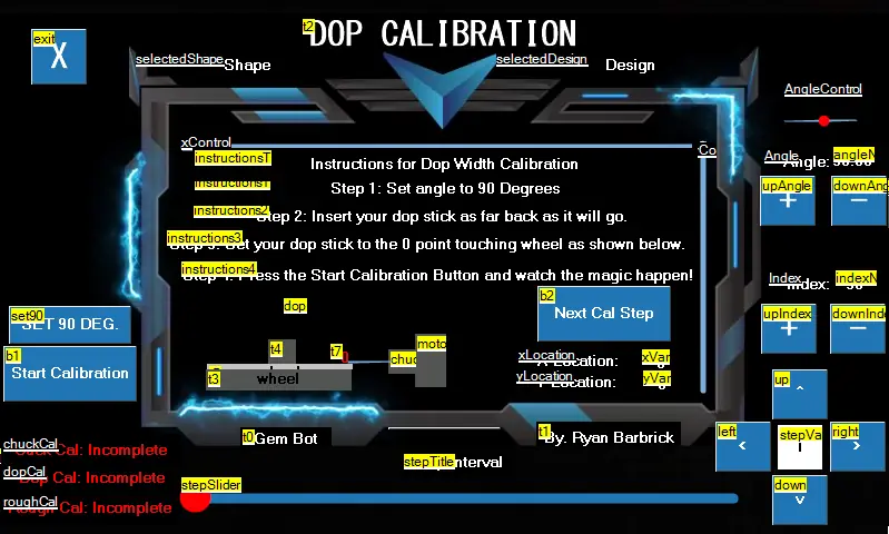
Here you can see how we will get the dop width data via the dop calibration page. All of these pages will be worked into the automated cut function process. But as you can see there will need to be some user interaction because we will be calibrating with the dop not in the machine, with the dop in the machine and with the dop with rough stone in the machine. Which will require some user interaction to achieve this data.
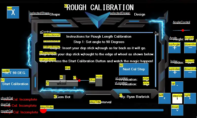
Here we can see the Rough Length Calibration page. This will be achieved by setting the dop with rough material attached to the edge of the lap and running the calibration function. We can then have the machine subtract the number of steps taken to reach the x and y limit switches from the dop length and dop with rough length to figure the length of the rough stone. This data will then be used in calculations for the automated cut functions.
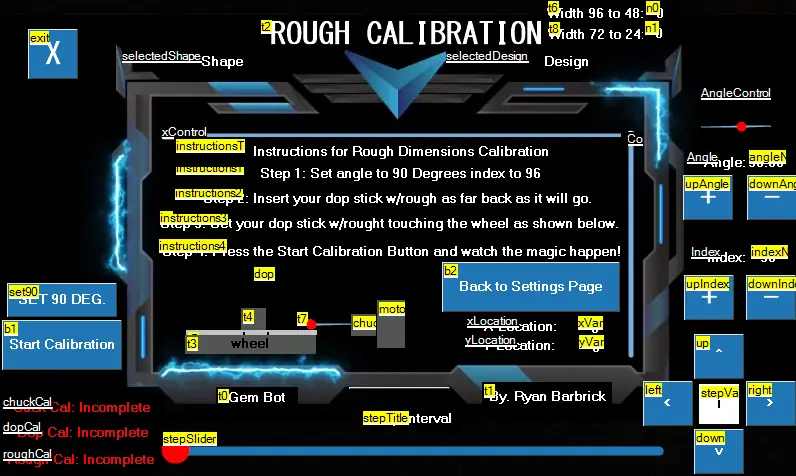
Here we can see the rough width calibration page. Where we will set the stone to the wheel at 4 different index locations to find the width of rough material. We will first set the stone to the wheel at the 96th index and run a home function, counting how many steps are needed on the x and y axis. Then the 48th index to get the number of steps it will take from the opposite side of the stone. From there we will be able to calculate with our dop calibration settings to determine the width of the stone from 96 to 48 index locations. We can then repeat the same process for 72 to 24 to get the next cross section width to determine an overall width for the stone. Some rough material may be larger on one side than the others that is why we take at least 4 index locations data to base our calculations on. We can now move onto selecting a shape and design via the Design Page. We will navigate back to the Home page where we have our To Do check list, use the right > arrow at the bottom right
of the screen to navigate to the Design Page.
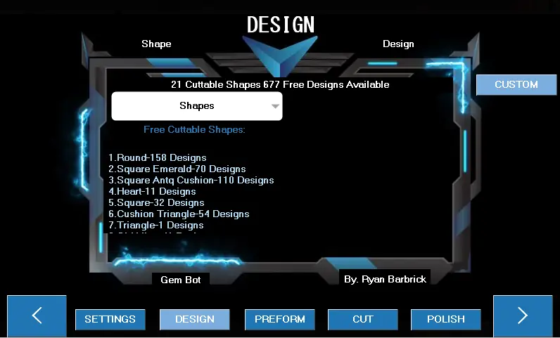
Here you can see the Design page. We have some text at the top that says there is 21 cuttable shapes and 677 Free Designs available to cut. There is a scrolling list of what designs are loaded up onto the touch screen by default. There is a Custom design button towards the right of the screen that allows users to input their own custom designs if they desire. I will walk you through selecting a shape. First we will click the drop down menu with title of “Shapes” on it. This will give us a list of all the shapes we can select from.
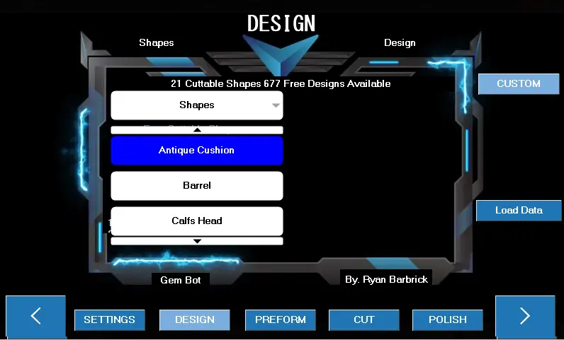
We can scroll through this list to select a shape. Once we have a selected shape. The text up top “Shapes” will change to the selected shape. I will select the Dodecagon shape as an example.
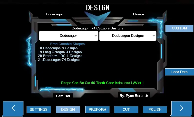
As you can see I have selected the Dodecagon shape and another drop down menu pops up to the right titled “Dodecagon Designs” This will include all the designs that we will be able to cut for the corresponding selected shape. You can also see in the upper left of the page the “Shape” text has now changed to Dodecagon because that is the shape we have selected to cut. If we select a different shape it will be changed to the newly selected shape. I will go ahead and select a Design now from the Dodecagon Designs list.
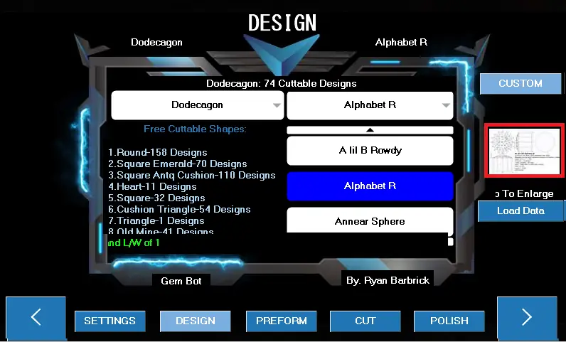
I have selected the “Alphabet R” Design since my name is Ryan I thought this would be a great selection for the user manual; ) example. You can now see that the text in the upper right that used to say “design” now says “Alphabet R” which is in fact our selected design. A preview image also pops up to the right so that we can see what we will be cutting. I will click the image to the right of the design drop down list now to make sure it matches the actual design we want to be cutting. The images here will not be as high quality as they are on the website but it will
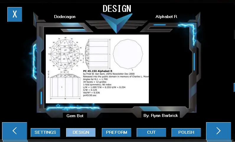
give us a good little preview.
You can see the preview design page has now popped up with a larger image of our facet diagram preview. Displaying the table, girdle and pavilion. We can press the X button in the upper left to get back to the design page.
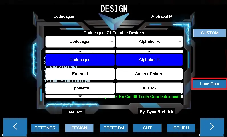
From there we can click the highlighted Load Data button.
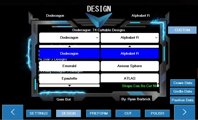
Once clicked the design data will be loaded from the sd card located on the back of the touch screen. There may be a slight delay when this data is loading. Once the data is loaded three buttons will appear that we can select from. The Crown Data, Girdle Data, and Pavilion Data buttons. I will select the Girdle Data button for example. Each button will load the corresponding page for whatever we desire to cut.
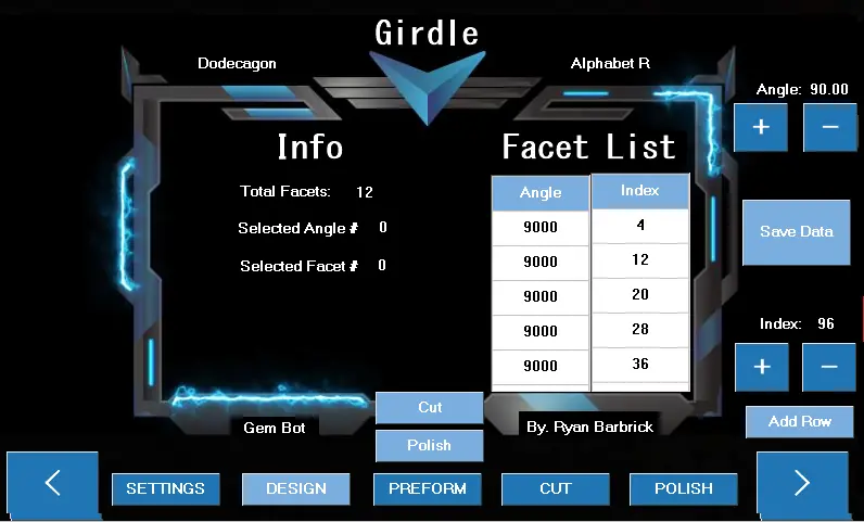
I have clicked the girdle data button and we are taken to the Girdle Data page where we can see some info for the girdle data based on the design we have selected. Some designs will not have any data populated in them yet. I have filtered the designs based on shapes and designs that have a Length and Width of 1 just to get the ball rolling on the whole project. I do have to manually enter all this design data converted over from their corresponding facet diagrams manually so bear with me if you come across a design without any data. Feel free to enter the data yourself if you would like. You can use the buttons to the right to add data to the Facet list and the gem bot will use these lists for its automated cut functions. You can see there are 12 girdle facets for this design. All the angles should be 90 since we are cutting the girdle of the stone.
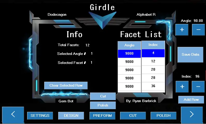
As you can see we can select data from the tables. We can remove and add data. A button appears to the left that we can use to delete selected rows. If we would like to add or change and index location we can use the buttons on the right to set the angle and index location then press add row. The data will be added to the bottom of the list. So if we want to change an index location or angle that is in the middle of the data table we will have to delete all data below and re populate the data tables based on whatever the facet diagram calls for for that specific design.
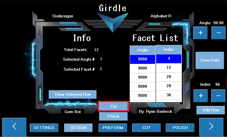
From this page we can go to the Cut and Polish Pages. I will click and go to the cut page now by pressing the “Cut” button there in the middle.
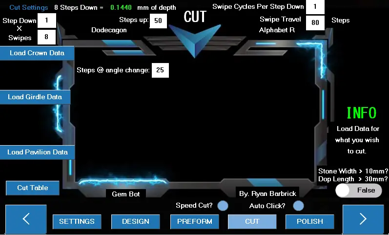
Now we are getting to the real fun stuff. The CUT Page. This is where the magic will really happen. You can see at the top there is various different cut settings that can all be modified based on whatever stone you are cutting. After we have preformed out stone round and selected our design we should be at this page. From here we will be able to Cut the Crown, Girdle, Pavilion and table. The polishing process will pretty much be the same but with different default cut settings up top. I have recently added a few things to this page like the Speed Cut and Auto Click cut functions. So since we have decided to load the girdle data, I will go ahead and show an example of how to cut the girdle. First I will go over the buttons on this page though so that you have an understanding of what buttons and what settings do what.
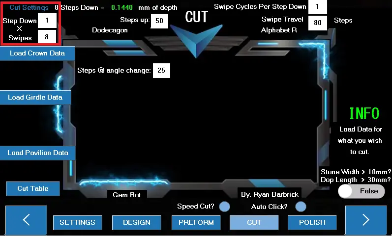
Highlighted above are the basic cut settings. We have our Step Down and Swipes. The default here is set to 1 step down per swipe and a total of 8 swipes on the lap. A swipe is an automated motion that the gem bot performs to mimic the swiping motion of a manual machine. This motion will consist of 80 steps left and 80 steps back right by default. The Swipe travel can also be altered as you can see there at the top right of the machine. Since we will be stepping down a total of 8 times, this will be cutting to a depth of .1440 mm. We can alter these two numbers if we desire different cutting depths or a more faster/aggressive cut. These settings will differ based on what grit lap you are using to remove material and what size stone you are trying to achieve. I like to start removing material with a 600 grit lap and work my way through higher grits into polish. The hardness of the stone that you are cutting will also play a roll in selecting these settings. If you are cutting a softer material and want a more aggressive fast cut you may want to adjust your steps down to maybe 2-4, this will drive the stone into the wheel more requiring less amount of swipes. As time goes on we will have more data available to users on what cut settings to use. Really though after you cut a few stones with the Gem Bot you will get
a good feeling for what you need to set your cut settings to.
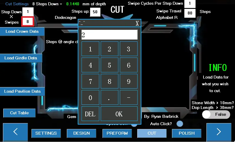
You can click on any of the white squares with black numbers in them to adjust the cut settings. A number pad will pop up where you can delete the number and add your desired number. I will
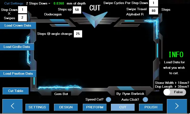
now change the swipes to 2 for less depth cut.
As you can see the green number up top has automatically changed. The machine made some calculations for you based on your cut settings that have been modified. We will now be making a total of 2 steps down. Removing only .036 mm of material. This is best for when we are in the higher grit laps, say 3000 to 8000 polish. When we already have our design cut in but we still need to remove some small amount of surface scratches left behind from prior grits. We can also change the swipe cycles per step down. And the swipe travel if we want a less aggressive cut during these higher grit cuts. Or maybe we are cutting a harder stone like sapphire, that requires more total swipes to ensure material removal. The steps up number is the default number of steps for the machine to step up during an index change. 50 steps up should be enough travel up away from the wheel for a stone that is preformed round. We may want to increase this number if we are going straight to cutting from a piece of rough that is not evenly shaped all the way around so that the machine has enough space to spin the stone around without it coming in contact with the wheel during an index change. The steps @ angle change is being used for the auto click function to determine how many steps need to be taken in either
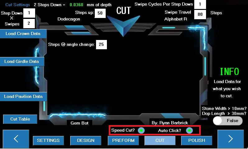
direction up or down based on a single step of the angle motor. This is still being tested by our testers as of now.
As you can see highlighted here I have selected to Auto Click during our girdle cutting. Since there is not an angle change where we will have to reset the stone back to the wheel, we can use the Auto Click function and it will loop through and cut every girdle facet for us based on our cut settings. I am now going to click the Load Girdle Data Button since we have adjusted our cut settings. We always want to adjust cut settings and select our cut type before loading the girdle data.
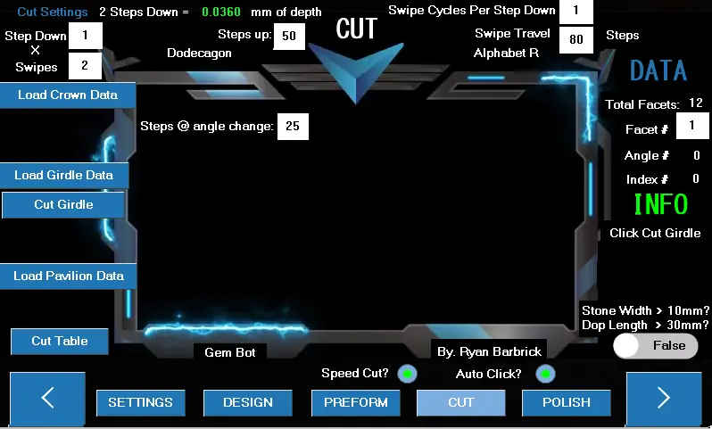
You can now see that the Cut Girdle Button has appeared. And some data has shown up on the right. We can see our total Facets and some Info below that instructs us what to do next. It looks like we should click the cut girdle button.
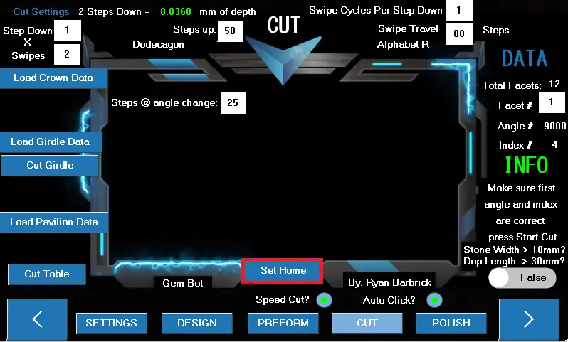
After clicking the cut girdle button the data for the first facet to cut will be populated as you can see to the right there. We will want to make sure this data matches our facet diagram before we start the cut. If this is correct and we have re looked over our cut settings we can click the set
home button that has appeared.
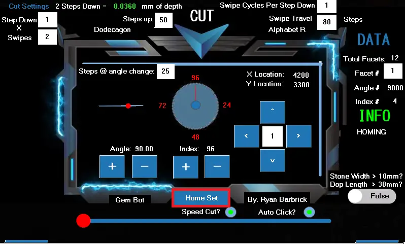
The machine will then start moving to its home position. After you can see that the machine has stopped moving and it has arrived at its home position. Click the home set button. We have to click this home set button because there may be varying times between homing functions based on where the machine is starting its home function from. We could of used pragmatic delays here but since the starting position when homing the machine differs we simply just made a home set button to let the machine know when the home function is complete.
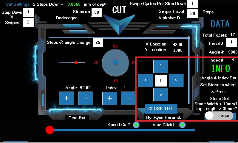
After the Home set button is pressed the machine will automatically set the angle and index to the corresponding data points. The first girdle facet will be cut at 90 degrees, so there was no angle change there from the home function, and the first index facet will be at the 4th index location. You can see that the digital readouts display the correct data and your physical index wheel should also represent the same data. Now we can move the stone close to the wheel. Remember the toggle switch from our manual controls? Here it is again. If we are cutting as tone that is larger than 10 mm and or we have a dop length that is larger than 30mm we will need to toggle this button to true so that the machine will not move the stone so close to the wheel but still close to the wheel. Saving us time and button presses for initially setting the stone to the wheel. So I will now go ahead and click the Close to 0 button. And get our stone set
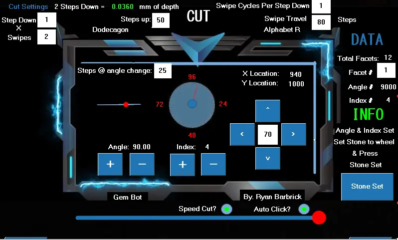
to the wheel.
You can see I have used the Left Button to move the stone a little closer to the wheel. I will probably still need to lower it a little to get it to set to the wheel. Once the stone is almost nearly at the wheel I will startup my drip motor and start spinning the wheel up. I will set my drip to the lowest amount of drip possible and the speed will differ based on what grit you are cutting at but I think 600-700 rpm is a good range to be at for speed. After the wheel is fired up and we are moving the stone down by 1 step and we start hearing the chatter at the wheel we can then click the stone set button. From there the machine will loop through its automated cut function. This is where the Gem Bot works its magic and where we can sit back and monitor its progress. If you are not using the speed cut function or auto click function. There will be some user interaction between index changes and angle changes. The gem bot will raise the stone after each facet and ask the user if they would like to continue the cut. In between facets the user could decide to inspect the facets, as long as they remember to set the index and angle back to what it was before they checked the stone. Or if the user decides they wish to power the machine down and continue cutting later they could set the index to 96 and power the machine down. They can take note of the facet they last cut and start the automated cut process of the
next facet number when they do decide to come back to the machine. As you can see the Facet number box to the right is black text with a white box background so that number can be altered before the cut sequence is started. There is no one way to go about cutting stones. The Gem Bot is here to help during the tedious steps. With precision and accuracy that humans just can't replicate over and over and over again without lots of practice and time into learning the feel for the skill , to provide digital readouts and automated movements.
I hope up to this point you have some better understanding of how to use the machine based on this example. I Do have more detailed videos on youtube and on the homepage of the website if you would like to see me demonstrating how to use the machine. I know some people would prefer a written user manual though. I will be adding to this user manual as time goes on. But feel free to download it and give it a read. Contact me with any questions that you may have. Or if I have missed anything that you believe the user manual needs. Cutting and polishing for the girdle, crown, pavilion should all be pretty similar based on the inputs needed from the user. It is your job to help the machine help you. As time goes on and we receive more data, the automated cut functions will grow smarter.
Maintenance
- Regular Cleaning: Clean the machine after each use to remove water that may of
sprayed over from the wheel, debris from cutting that may of collected in the drip pan/drain tube during the cut process. You can use a rag and soap and water for cleaning the machine.
- Lubrication: Periodically lubricate moving parts such as the x and y ball screws and
guide rails. You can use any form of wd40 or thin grease to keep these components lubed up.
- Inspection: Regularly inspect the machine for wear and tear, and replace any worn
components as needed.
Troubleshooting
- Machine Not Starting: Check the power connection and ensure the machine is plugged
in.
- No Power To Touch Screen: Check the power connection and ensure the touch screen is
plugged in.
- Machine Running past its limit switch points: Run a switch test to see which limit switch
may not be functioning correctly. Double check your wiring to make sure the limit switch is plugged in. Make sure the trigger and limit switch are able to come in contact with each other.
- Inconsistent Cuts: Verify that the gemstone is securely attached and aligned properly in
the chuck. Make sure that you have preformed your stone correctly and that it is in fact the shape you need. Double check the facet diagram via the website and make sure that the data table for your selected design matches the facet diagram on the website. It is possible that the data table on the touch screen is incorrect.
- Unusual Noises: Stop the machine immediately and inspect for any obstructions or
loose parts. Contact Ryan Barbrick and let him know where the abnormal noise is coming from. He will guide you through the troubleshooting process.
Contact and Support
For further assistance, please contact:
- Email: BarbrickDesign@gmail.com
- Website: Merlin's Gem Bot
Stay updated with the latest news and tutorials by following us on YouTube and Instagram.
Identifying Parts of the Machine
Parts List
- Arbor Thumbscrew
- Bottom Wide Plate
- Brackets for Inverter and Controller
- Drip Tube Clamp
- Index Motor/Frame and Back Plate
- LED Screen
- Touch Screen
- Front Side Support Rail
- Y axis Mid Platform
Y axis Support Platform
Rear support rail
Right side support rial
Riser block
Top Horizontal Stiffener Plate
Top Y axis Motor Support Bracket
Top Y axis Motor End Plate
Vertical Rail Offsets
Arduino Box
Limit Switch/cover
Y Axis Limit Switch/Mount
X Axis Limit Switch/Mount
Angle Control Limit Switch Mount
Angle Control Limit Switch Trigger
Upper frame assembly
X axis Ball screw/mounts/connector
X axis Nema 17 Stepper motor
Y axis Ball screw/mounts/connector
Y axis Nema 17 Stepper motor
Index Stepper Motor
Chuck
Collet Set
Dop Stick
Angle Control Nema 17 Stepper Motor
5:1 Planetary Gear Box for angle Control
Electric direct drive motor for Wheel
Arbor screw for attaching Lap
Master Lap
Topper Lap
Copper Polishing Lap
Drip Pan
Drip Pan Riser
Upper guide rails
Lower guide rails
Motor control/power inverter
Top Drawer
Lower Drawer
Led Light on flex arm
Drip arm
Drain tube
Water pump
Water drip switch
Water reservoir Send/Return
Arduino Board
Arduino Motor shield x 2
Motor driver
Power inverter
Drip motor power inverter/controller
Wiring
Led lights inside lower base
Led light controller
Smart surge protector power strip
USB Cable for updating arduino
SD Card for updating touch screen
SD Card for storing Designs
Misc tools for maintaining the machine
© Ryan Barbrick / Barbrick Design · Merlin's Gem Bot